Wire Colour and Polarity Marking on the DC Side
Colour is the simplest polarity marker on a DC string and the easiest one to get wrong, because a sheath that fades or a marking that stops short leaves the next technician guessing at a live conductor. The published range from KUKA CABLE is short and specific - black or red, in single-core and twin-core versions - and the same pages publish the bend radius, which is what keeps a marking legible at a termination. The manufacturer states the sheath print survives a 2,000-hour xenon test, arranged on its solar wire range and described as equal to about 360 weathering cycles.
Key takeaways
- The manufacturer publishes two colours for its solar cable, black and red, in single-core and twin-core versions; no third colour is listed.
- No page maps a colour to positive or negative, so the polarity convention has to be fixed on the drawing and confirmed with the supplier.
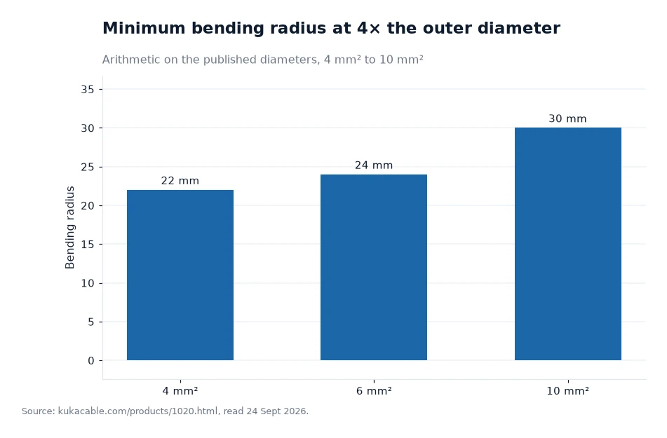
- The bend radius is published as 4 times the outer diameter, which is 22 mm for the 4 mm² size with its 5.5 mm outer diameter (my own arithmetic).
- Marking survives or fails with the sheath: the published UV accelerated weathering test and the 2,000-hour xenon exposure are what a faded print fails.
What is published about colour
The solar cable pages describe a construction offered in black or red, with single-core and twin-core versions of the same sizes. Those are the only colours the manufacturer publishes for this range, and the pages do not add a printed marking convention on top of them. Nothing on the site states that red is positive on a DC string or that black is negative.
That silence is normal and it is worth respecting. Colour conventions for DC conductors vary between markets, and they vary again between a rooftop string and a utility-scale block. A buyer should print the convention on the drawing, name it in the purchase order and ask for it to be confirmed in writing, so the drum that arrives matches the convention the electrician will work to.
Why polarity matters more on DC
An AC arc tends to extinguish as the current crosses zero, which happens many times a second. A direct current has no such crossing, so a reversed or loose termination on the DC side can sustain an arc instead of clearing it. The practical defence is unambiguous marking at both ends of every string, plus a connection method that cannot be mated the wrong way round.
The manufacturer's published list of tests for PV cables, on its laboratory pages, includes cable connectivity among the items it checks, alongside conductor resistance, insulation resistance, dielectric strength, tensile strength, heat resistance, flame retardant performance, environmental adaptability and corrosion resistance. Termination quality is therefore treated as part of the product on the laboratory pages, which is a fair reminder that polarity is settled at the joint as much as on the sheath.
Marking has to outlive the weather
A printed line on a sheath competes with sunlight, heat and ozone for twenty-five years or more, and the published tests describe how that is approached. UV accelerated weathering is one of the nine test pages, and a 2,000-hour xenon lamp exposure - described as equivalent to about 360 weathering cycles - is being arranged on the company's solar cables.
The material behind the print is described as electron-beam cross-linked XLPO, low smoke halogen free, with elongation stated as reaching up to 185% against the 125% required by EN 50618. A sheath that keeps its elongation also keeps its surface, which is what the print sits on. The company's certificates listing puts TUV EN 50618 among more than 30 types of certificate covering TUV, IEC, CE, SAA and UL, which is the paperwork to ask for when marking durability is on the specification.
The bend that decides what you can read
Every termination needs working space, and the published minimum is 4 times the outer diameter. For the commonly used sizes that means 22 mm at 4 mm² with its 5.5 mm diameter, 24 mm at 6 mm² at 6.0 mm and 30 mm at 10 mm² at 7.5 mm, all taken from the manufacturer's cross-section table and multiplied out by me. Installers who bend tighter than that are not only stressing the insulation; they are also pushing the print into the shadow of a tray wall where the next person cannot read it.
Ambient limits are published as -40 °C to +90 °C, with +120 °C permitted over 20,000 hours and +250 °C for 5 seconds in short circuit. A cable bent cold, in a tray, at a radius below the published figure is the case where a marking question becomes a warranty question, because the surface has been deformed before the print ever aged.
| Nominal cross-section | Nominal overall diameter | Minimum bend radius at 4x diameter | What that means at a termination |
|---|---|---|---|
| 1.5 mm² | 4.6 mm | 18.4 mm | Rounded radius, single-core sensing runs |
| 2.5 mm² | 5.0 mm | 20.0 mm | Short jumper lengths inside a combiner |
| 4 mm² | 5.5 mm | 22.0 mm | The usual rooftop string size |
| 6 mm² | 6.0 mm | 24.0 mm | Longer runs where drop matters |
| 10 mm² | 7.5 mm | 30.0 mm | Home runs towards the inverter |
| 16 mm² | 8.8 mm | 35.2 mm | Array-side feeders and larger harnesses |
Worked example
Picture two 4 mm² cables bent the same way inside a tray. Each needs a 22 mm radius at the published construction, so the pair spans about 44 mm across the bend (22 plus 22 equals 44; my own arithmetic, assuming both bends lie in the same plane and no clearance allowance is added). A 50 mm tray therefore takes the pair with a few millimetres to spare, but not a third cable, which would need about 66 mm (my own arithmetic). Sizing the tray from the published radius is quicker than discovering the problem on site.
The temperature figures can be compared in the same spirit. The ambient limit is +90 °C, which is 363.15 kelvin, and the short-circuit allowance of +250 °C for 5 seconds is 523.15 kelvin, about 1.44 times the ambient limit (273.15 is added to each Celsius figure before dividing; my own conversion, not a published ratio). The gap is the margin the insulation is given for a fault, and it is the reason a marking or a joint that is only rated for ambient conditions should never be described as fault-rated.
Frequently asked questions
What colours does the manufacturer publish for its solar cable?
Two: black and red, in single-core and twin-core versions of the same sizes. The site does not publish a rule that maps either colour to positive or negative, and no third colour is offered for the range, so a polarity convention has to be written on the project drawing and confirmed with the supplier before the drums are produced.
How much space should be left at a bend on the DC side?
The published figure is 4 times the outer diameter, which works out at 22 mm for the 4 mm² size with its 5.5 mm published diameter, 24 mm for 6 mm² at 6.0 mm and 30 mm for 10 mm² at 7.5 mm (my own arithmetic from the published diameters). Because it is a radius, two cables bending the same way need roughly 44 mm across for 4 mm² before any clearance is added.
What to write into the drum order
State the polarity convention, the colour, the size, the lengths and the marking text on the drawing, then ask for a sample end so the print can be checked before production. Ask for the certificate that applies to the batch and the test report behind it, including the UV and xenon work, because marking durability is the one property that cannot be inspected on arrival. The manufacturer's contact points are published on every page, and its product consultant can confirm the convention before the order is placed.
Every number in this piece on DC polarity marking comes from the manufacturer's own website; the bending radii for 4, 6 and 10 mm² here were consulted 24 Sept 2026[1].